
This hobby started with my desire to own a 5150 with a green phosphor monitor as that’s the system I first learned on back in high school. There are lots of nuances to owning and maintaining a 5150 in the modern age – as there would be for the very first PC ever released.
Switch Blocks
There are two sets of 8 switches each on the 5150 PC motherboard and they aren’t labeled in any meaningful way whatsoever.
Switch Block 1 [SW1]
Of the two blocks of switches, this is the one closer to the middle of the board, not on the edge near where the power supply sits. It’s very close to the first slot on the motherboard, and it provides general control over the way your 5150 is configured:
- SW1.1
- OFF = one or more Floppy Drives are installed
- ON = no Floppy Drives are installed
- SW1.2
- OFF = Math Co-Processor (8087) installed
- ON = No Math Co-Processor (8087) installed
- SW1.3 and SW 1.4
- 1.3 OFF, 1.4 OFF = All four banks of RAM populated
- 1.3 ON, 1.4 OFF = First three banks (0, 1 and 2) populated
- 1.3 OFF, 1.4 ON = First two banks (0 and 1) populated
- 1.3 ON, 1.4 ON = Only bank 0 populated
- SW1.5 and SW 1.6
- 1.5 OFF, 1.6 OFF = Monochrome (MDA, Hercules) Graphics Card
- 1.5 OFF, 1.6 ON = CGA Graphics Card, 40 columns, 25 lines
- 1.5 ON, 1.6 OFF = CGA Graphics Card, 80 columns, 25 lines
- 1.5 ON, 1.6 ON = EGA or VGA Graphics Card (any card with it’s own BIOS ROM)
- SW1.7 and SW1.8
- 1.7 ON, 1.8 ON = One Floppy Drive
- 1.7 OFF, 1.8 ON = Two Floppy Drives
- 1.7 ON, 1.8 OFF = Three Floppy Drives
- 1.7 ON, 1.8 ON = Four Floppy Drives
Notes:
SW 1.1, 1.7 and 1.8 need to be set correctly to have access to your floppy drives. In my experience, however, having them set for too many drives (or drives present when there are none) only really results in a “missing floppy drive” error at boot, which is easy enough to ignore while you’re troubleshooting.
SW 1.3 and 1.4 default to ON because that bank of RAM is soldered to the board – you can’t avoid having those installed. The other three banks are socketed and can be populated with 9 4164 chips per bank to add 64K per bank for a maximum of 256K.
Footnote – all of these are based on the later 64k-256k models, as those are the only ones I have experience with. On 16k-64k models I suspect they are similar, but YMMV.
If you are going to rock the original dual-head setup, with one monochrome and one color display, set SW 1.5 and 1.6 based on the color monitor setup you’re going to be using – the monochrome display will come along for free.
Switch Block 2 [SW2]
The second block of switches lives on the edge of the motherboard, close to the PSU and the power connector. Where the first batch of switches is difficult to get at with drives installed, this one is nearly impossible among the tangle of power cables and ribbon cables, so set it early in your build process! This one is strictly about the RAM installed. Unlike modern PCs, you have to tell it how much to expect, in even more detail than you did on SW1.
For the boards I have experience with (see note above), only the first five switches matter – IBM just didn’t want to source a different size switch bank for this one – buy in bulk! – so SW2.6, 2.7 and 2.8 can be whatever you want them to be.
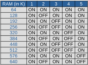
Of particular note, only the first four are available options to you unless you add a memory expansion card (RAM+, AST SixPak or the like) and each of those vendors handles things differently in how they want you to configure your machine – this time, definitely read the friendly manual. Some will want you to set this to the total RAM, some to the amount installed on the system itself without the card.
XT-IDE and Power Supplies
I’ve not seen a lot of discussion about this, but I struggled mightily for a long time, burning many hours, to figure this out so I figured I’d share it just in case anyone else runs into it.
If you install an XT-IDE BIOS enabled card into your system – whether that be an XT-CF card, an XT-IDE card or just putting the BIOS chip on a network adapter – if you find that everything works, you can see the card, format it, create and delete files and the whole nine, but you can’t boot from it for love nor money, the issue may just be your power supply.
Being the alpha geek that I am, I picked up a third-party PSU for my first 5150. Not only did I have dreams of installing a hard drive in the system, which the default 63.5 watt PSU would not have allowed, I also wanted additional connectors both for that drive, for a Gotek floppy emulator, and eventually for my XT-CF’s CF adapter. It worked great (emphasis on worked as it has since perished and awaits a repair at a future date) and was whisper quiet.
In addition, in the meantime I also acquired another 5150 that came with a third party PSU – louder, but a full 200 watts of power. It too worked great in either machine.
I never noticed any trouble at all and never once thought that the issues I was having getting my machines to boot from the XT-CF had anything to do with it, but after I had replaced LITERALLY EVERY OTHER COMPONENT and had the same results, the only thing left to try was the power. So I put the original PSU back in and… sunnovabitch it worked. Booted right up first try, no further configuration changes required.
I tested the other two PSUs for power and they were well within normal specs for voltage, but something my low-end multimeter couldn’t show me was that the power was noisy. It was inconsistent in some way or another and just enough so to cause issues with the timing of events in the system.
So, take this lesson if you are in the same boat. If your XT-IDE related card isn’t allowing you to boot, check your power. It may be the issue hiding in plain sight.